| |
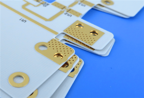
Rogers RO4835 2-Layer 0.6mm Immersion Gold PCB – Automotive Radar & RF Applications
1. Introduction to Rogers RO4835 PCB
Rogers' RO4835 laminate offers enhanced stability at high temperatures and is more resistant to oxidation than other hydrocarbon materials. RO4835 laminates share similar electrical and mechanical properties with RO4350B laminates and are designed for high frequency performance and cost-effective circuit fabrication. It uses standard epoxy/glass (FR-4) processes and is competitively priced. RO4835 laminates are a low loss material that offer low cost circuit fabrication. These laminates are available with Rogers proprietary LoPro Reverse treated copper foil, ideal for applications requiring low insertion loss.
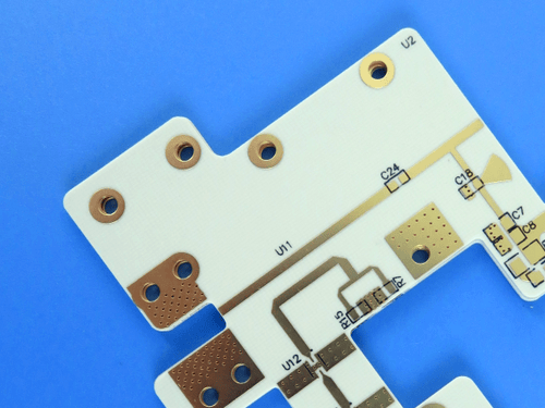
This 2-layer rigid PCB is constructed entirely with RO4835 as the core material, making it ideal for demanding automotive radar, point-to-point microwave, and phased-array radar applications. The material's low loss and tight Dk tolerance ensure excellent signal integrity and controlled impedance performance.
2. Key Features of Rogers RO4835 PCB
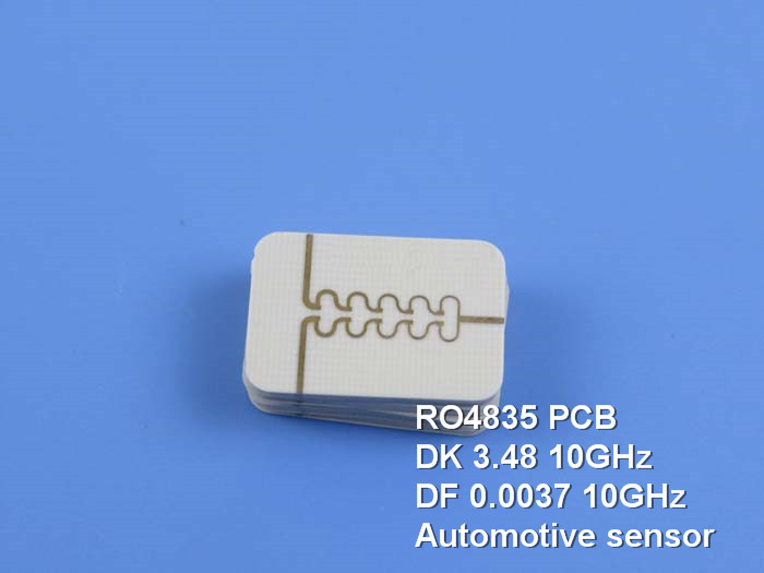
RoHS compliant for applications requiring UL 94 V-0 IPC-4103 compliant Dielectric constant (Dk) of 3.48 ± 0.05 Dissipation factor of 0.0037 at 10 GHz Glass Transition Temp (Tg) >280 °C TMA Coefficient of Thermal Expansion: X:10 ppm/°C, Y:12 ppm/°C, Z:31 ppm/°C Significantly improved oxidation resistance compared to typical thermoset microwave materials Low moisture absorption: 0.05% Thermal conductivity: 0.66 W/(m·K) CAF resistant
3. Benefits of Rogers RO4835 PCB
Significantly improved oxidation resistance — designed for performance sensitive, high volume applications Low loss — excellent electrical performance allows application with higher operating frequencies; ideal for automotive applications Tight dielectric constant tolerance — controlled impedance transmission lines Lead-free process compatible — no blistering or delamination Low Z-axis expansion — reliable plated through holes Low in-plane expansion coefficient — remains stable over entire range of circuit processing temperatures Standard FR-4 processing — no specialized via preparation required Competitive pricing — cost-effective high frequency performance
4. PCB Construction Details
| Item | Specification |
|---|
| Base material | Rogers RO4835 (hydrocarbon ceramic laminate) |
| Layer count | 2-layer |
| Board dimensions | 45mm x 83.69mm = 1 PCS, ±0.15mm |
| Minimum Trace/Space | 5/6 mils |
| Minimum Hole Size | 0.2mm |
| Blind or buried vias | No |
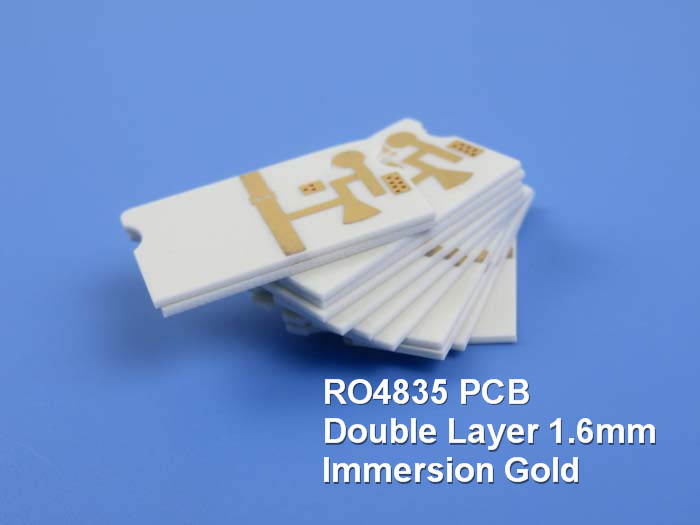
| Finished board thickness | 0.6mm (20 mil core) |
| Finished Cu weight | 1 oz (35 μm / 1.4 mils) all layers |
| Via plating thickness | 20 μm |
| Surface finish | Immersion Gold |
| Top Silkscreen | Black |
| Bottom Silkscreen | No |
| Top Solder Mask | No |
| Bottom Solder Mask | No |
| Silkscreen on solder pads | No |
| 100% Electrical test | Used prior to shipment |
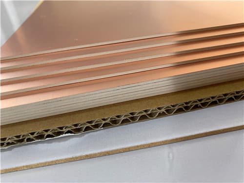
5. PCB Stackup (2-Layer Rigid Structure)
| Layer | Material | Thickness |
|---|
| Layer-1 (Top) | Copper | 35 μm (1 oz) |
| Dielectric | RO4835 | 0.508 mm (20 mil) |
| Layer-2 (Bottom) | Copper | 35 μm (1 oz) |
6. PCB Statistics
| Parameter | Value |
|---|
| Components | 18 |
| Total Pads | 32 |
| Thru Hole Pads | 24 |
| Top SMT Pads | 8 |
| Bottom SMT Pads | 0 |
| Vias | 9 |
| Nets | 2 |
7. Rogers RO4835 Material – Product Introduction
Rogers' RO4835 laminate offers enhanced stability at high temperatures and is more resistant to oxidation than other hydrocarbon materials. RO4835 laminates share similar electrical and mechanical properties with RO4350B laminates and are designed for high frequency performance and cost-effective circuit fabrication. It uses standard epoxy/glass (FR-4) processes and is competitively priced. RO4835 laminates are a low loss material that offer low cost circuit fabrication. These laminates are available with Rogers proprietary LoPro Reverse treated copper foil, ideal for applications requiring low insertion loss.
As part of the RO4000® hydrocarbon ceramic laminate family, RO4835 laminates are designed to offer superior high frequency performance and low cost circuit fabrication. Low dielectric loss allows RO4000 series material to be used in many applications where higher operating frequencies limit the use of conventional circuit board laminates. The expansion coefficient of RO4000 material is similar to that of copper which allows the material to exhibit excellent dimensional stability, a property needed for mixed dielectric multi-layer board constructions.
8. Features and Benefits Summary
| Feature | Benefit |
|---|
| Significantly improved oxidation resistance | Designed for performance sensitive, high volume applications |
| Low loss (Df 0.0037 @ 10 GHz) | Excellent electrical performance at higher operating frequencies; ideal for automotive |
| Tight Dk tolerance (±0.05) | Controlled impedance transmission lines |
| Lead-free process compatible | No blistering or delamination |
| Low Z-axis CTE (31 ppm/°C) | Reliable plated through holes |
| Low in-plane CTE (X:10, Y:12 ppm/°C) | Stable over entire range of circuit processing temperatures |
| CAF resistant | Enhanced reliability in harsh environments |
| UL 94 V-0 compliant | RoHS compliant flame-retardant technology |
9. RO4835 Typical Properties (Data Sheet)
| Property | Typical Value | Direction | Units | Condition | Test Method |
|---|
| Electrical Properties |
| Dielectric Constant, εr (Process) | 3.48 ± 0.05 | Z | — | 10 GHz/23°C | IPC-TM-650 2.5.5.5 |
| Dielectric Constant, εr (Design) | 3.66 | Z | — | 8 GHz-40 GHz | Differential Phase Length Method |
| Dissipation Factor, tan δ | 0.0037 | Z | — | 10 GHz/23°C | IPC-TM-650 2.5.5.5 |
| Thermal Coefficient of ε | +50 | Z | ppm/°C | -100°C to 250°C | IPC-TM-650 2.5.5.5 |
| Volume Resistivity | 5 × 10⁸ | — | MΩ·cm | COND A | IPC-TM-650 2.5.17.1 |
| Surface Resistivity | 7 × 10⁸ | — | MΩ | COND A | IPC-TM-650 2.5.17.1 |
| Electrical Strength | 30.2 (755) | Z | KV/mm (V/mil) | — | IPC-TM-650 2.5.6.2 |
| Thermal Properties |
| Glass Transition Temp (Tg) | >280 | — | °C TMA | A | IPC-TM-650 2.4.24.3 |
| Decomposition Temp (Td) | 390 | — | °C TGA | — | ASTM D3850 |
| CTE (X-axis) | 10 | X | ppm/°C | -55 to 288°C | IPC-TM-650 2.4.41 |
| CTE (Y-axis) | 12 | Y | ppm/°C | -55 to 288°C | IPC-TM-650 2.4.41 |
| CTE (Z-axis) | 31 | Z | ppm/°C | -55 to 288°C | IPC-TM-650 2.4.41 |
| Thermal Conductivity | 0.66 | — | W/(m·K) | 80°C | ASTM C518 |
| Mechanical & Physical Properties |
| Copper Peel Strength | 0.88 (5.0) | — | N/mm (pli) | after solder float, 1 oz EDC Foil | IPC-TM-650 2.4.8 |
| Moisture Absorption | 0.05 | — | % | 48 hrs immersion, 50°C, 0.060" sample | ASTM D570 |
| Density | 1.92 | — | gm/cm³ | 23°C | ASTM D792 |
| Flammability | V-0 | — | — | — | UL 94 |
| Lead-Free Process Compatible | Yes | — | — | — | — |
10. Primary Application Areas
11. Quality Assurance
Type of artwork supplied: Gerber RS-274-X Accepted standard: IPC-Class-2 Service area: Worldwide 100% Electrical test prior to shipment IPC-4103 compliant (slash sheet /11)
12. Standard Thicknesses, Panel Sizes & Claddings
| Parameter | Options |
|---|
| Standard Thicknesses | 0.0066" (0.17mm), 0.010" (0.25mm), 0.020" (0.51mm), 0.030" (0.76mm), 0.060" (1.52mm) |
| Standard Panel Sizes | 12" x 18" (305 x 457mm), 24" x 18" (610 x 457mm), 24" x 36" (610 x 915mm), 48" x 36" (1219 x 915mm) |
| Standard Claddings | ½ oz (18μm) HH/HH, 1 oz (35μm) H1/H1 (LoPro Reverse treated copper foil available) |
|
|